CHISWICK REACH STEREO VALVE COMPRESSOR – February 2000 – Sound on Sound
Hugh Robjohns tries out a new stereo valve compressor hand-built in Britain, which shines both in the studio and the mastering room.
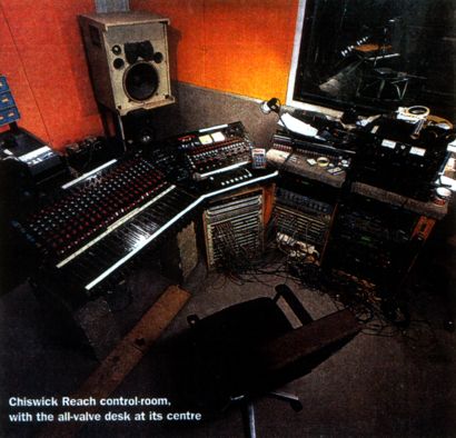
The design of the Chiswick Reach Stereo Valve Compressor benefits from over 65 man-years of experience in valve-based professional audio equipment, going back to the design in the late ’60s and early ’70s of the 24-track all-valve studio at Chalk Farm — apparently recognised as the reggae studio of the time. Although the stereo valve compressor is the first commercial unit from Chiswick Reach, several other projects are nearing completion or under development including a valve-based distortion unit, an equaliser and a mic amp chain.
The unit reviewed here is a purist no-compromise all-valve device with a very high-quality signal path. All of the active circuitry operates in a true balanced Class-A mode and it is entirely transformer-coupled, with two groups of three valves employed in the two matched channel paths. Attention to detail is apparent throughout the unit, but nowhere more so than in the audio transformers. These have been custom-engineered to ensure an extended frequency response at both ends of the spectrum and to accommodate high signal levels without saturation or distortion. In fact, the published specifications quote distortion as better than 0.08 percent with +8dBu input level and 5dB of compression — evidence that the Chiswick Reach is a very clean signal processor indeed!
The signal-path valves are all selected and matched for the best noise and distortion, as well as to make sure that the channel gains track properly in the linked-stereo mode. Although replacing matched pairs of valves is relatively expensive, the balanced push-pull circuit topology of the unit is claimed to provide a useful valve life of at least three years between replacements, so the running costs are not too daunting. With similar attention to detail, all of the passive components have been carefully selected for low noise and negligible signal coloration.
Get Yourself Connected
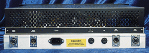
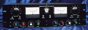
The unit is housed in a traditional valve amp chassis. The substantial 3U rackmounting case has an enclosed lower chassis with a perforated top cover providing the necessary ventilation for the valves. The rear panel carries the balanced input and output XLR connectors for each channel with a standard IEC mains connector and its associated fuses (mains input and separate HT fuse), though no side-chain input is provided. The front-panel finish is a durable black paint, contrasting with the white legends and gain-reduction meters, and the full height of the front panel is used to support the self-explanatory operational controls (see below).
In the tradition of valve chassis construction, the top surface of the base section carries the valves, reservoir capacitors and transformers, all neatly and symmetrically laid out. As mentioned earlier, the input and output transformers are substantial custom-designed devices, which apparently won’t saturate below +24dBu, suffer only one degree phase error between 10Hz and 25kHz, and exhibit -3dB points only at 4Hz and 35kHz. Impressive beasts indeed, and fully shielded with mu-metal, a compound made from 80 percent nickel and 20 percent iron which protects sensitive electronic equipment from electromagnetic interference.
For the glassophiles amongst you, the rectifier valve in the shared PSU is a 5AR4/GZ34, while the audio channels are processed through a 6BQ7 (gain control valve), an EB91 (side-chain rectifier) and a 12AT7/ECC81 (output valve). The interior of the chassis carries the remaining components, hand-wired on tag strips, but the promise of 300 Volts of HT was all the persuasion I required not to open this box to examine the internal construction more closely!
The gain-reduction meters are not just VU meters modified for the task, but actually show the cathode current of the 6BQ7 gain-controlling valve. As the performance of these valves alters with age, it becomes necessary to trim the meter circuit, for which purpose a pair of electronic zeroing trimmers has been provided in the centre of the front panel, although they are not marked to indicate which control relates to which meter.
Down The Signal Path
The manual for the stereo valve compressor is pretty thorough in its descriptions, though the lack of any diagrams or pictures does make it a little uninviting and inaccessible. However, it provides an excellent explanation of the function of each control in the context of its position in the signal path, for those owners who prefer to read the book before plugging the unit in! For those who would rather just plug it in and fiddle with it, operation is very intuitive and it seems to be quite indestructible. The manual also provides a comprehensive list of recommended starting points for different instruments and sound types.
| “…an impressive processor by anyone’s standards, capable of everything from the most gentle, transparent dynamic squeezing to the most full-on, heavy and dirty processing.” |
Following the manual’s example, I’ll trace the signal path through the compressor: the first thing the input signal ‘sees’ is the bypass toggle switch mounted below and to the right of the large input gain control. This provides a hard-wired through-route from input to output socket. A switchable 10dB attenuator on an identical toggle switch to its left follows in the audio chain. This is intended partly to avoid any risk of saturation of the input transformer by high-level transients, but its main function is to allow the Input Level control to be used around its most accurate central region, even with high-level signals.
The Input Level control is a vast, retro-styled knob which dominates the front panel. The amount and nature of compression can be determined largely from the setting of this parameter, justifying its dominance. The Attenuator and Input Level controls are not, strictly speaking, true balanced attenuators, but are nevertheless completely satisfactory in operation with all kinds of output stages. Following this level preconditioning the signal passes through the input transformer and into the 6BQ7 gain-controlling valve in a balanced Class-A circuit topology.
The Threshold control sets the sensitivity of the compression side-chain and therefore determines the signal level at which compression starts. This control interacts with the Input Level setting, and so is scaled simply from 1 to 10. The compression ratio is varied continuously depending on how hard the device is driven, and ratios between 1:1 and about 25:1 are available by manipulating the input level and the threshold. The result is a seamless variation in the amount of ‘squash’ performed by the machine. However, the two controls also alter the quality of the sound in different ways — increasing the Input Level not only adds to the compression but also drives the valve circuits harder, producing a slightly ‘dirtier’ sound. Increasing the Threshold control produces more compression in much the same way, but the sound remains cleaner and more neutral.
The dynamic controls — Attack and Release — operate on the side-chain circuitry to programme the response and recovery times, respectively, of the compressor. Both controls are scaled arbitrarily between ‘fast’ and ‘slow’, although the Attack control has an additional backstop switch which engages a ‘Thump’ mode! The time constants of the Attack control are not given in the specifications, but range approximately from tens of microseconds up to about 20mS. The Release times span 0.25 to 2.5 seconds and, unusually, there is no ‘automatic’ or programme-controlled recovery mode. The ‘Thump’ mode apparently changes the operating impedance of the side-chain circuit in such a way that it permits high-frequency overshoots whilst still clamping low-frequency signal peaks. This lends a very percussive quality to the compressed sound that can be particularly useful in creating a dynamic, ‘clicky’ drum sound — more of a production effect than normal, straight compression.
The output control is a balanced attenuator positioned after the output transformer to adjust the signal level leaving the machine. Its rotary switch operates in 4dB steps between -8 and +4dBu and, although rather more crude than the typical ‘make-up gain’ facility of most compressors, I found it adequate for approximate matching of signal levels. After all, the returns of most consoles would be able to accommodate any remaining level discrepancies without too much trouble. Having said that, Chiswick Reach are currently reviewing this aspect of the design to see if future versions of the compressor could have better switching resolution for output gain.
 Each channel has its own gain-reduction meter driven directly from the gain-controlling valve. The nature of the circuitry means that it is not possible to reconfigure this meter to view the input or output signal levels, but most consoles with which the compressor would be used have adequate send and return metering facilities already. The meter is calibrated from 0dB to -20dB in a very non-linear manner, although this is actually a blessing as it displays relatively mild degrees of compression very clearly and makes heavier compression look positively scary!
Lurking in the centre of the unit, between the channel meters, are the Power and Stereo Link switches. The powered condition is indicated by a small light embedded in the Chiswick Reach logo (marking “the exact spot on the banks of the river Thames where the compressors are built”). The Stereo Link mode ties the side-chains of the two channels together to ensure stereo-image stability. However, the controls of both channels need to be set identically to match the compressor’s response to signal peaks in each channel.
Pushing It To The Limit
The Chiswick Reach is capable of some very subtle but effective compression — the kind of processing which seems barely noticeable, but makes all the difference to a completed track! With gentle compression settings the valve processing is extraordinarily transparent and neutral — none of that heavy, rich, stereotypical valve sound which so many retro units try to produce — yet it still manages to add a delicate warmth to the sound which somehow seems to improve the cohesiveness of any track passed through it. At the opposite extreme, with everything turned up full, the machine really growls! It gets thick and dirty and beefs things up in a totally usable way — everything you’d want a good valve unit to do.
I used the Chiswick Reach mostly for fairly subtle mastering applications — light classics, choral and small orchestral music. It worked extremely well, producing just the right amount of warmth without losing any detail or finesse. With very gentle compression it always remained clean and free of obvious colorations too. On solo instruments, the compressor could be worked a lot more and virtually every setting produced an effect which was usable in one context or another. Nothing ever seemed to sound bad, although there were obviously optimised settings for any given source, particularly when it came to tuning the attack and release controls.
Overall, the unit’s wide bandwidth and phase-linearity provided excellent sound quality, with the bypassed and processed sound being extremely close at low compression ratios. If anyone needed convincing that valve technology is capable of matching the best of the solid state and 24/96 digital camps, this unit would be a good one to call upon!
Whether for mastering applications or general studio work, the Chiswick Reach Stereo Valve compressor is an impressive processor by anyone’s standards, capable of everything from the most gentle, transparent dynamic squeezing to the most full-on, heavy and dirty processing. It’s not cheap, but costs a lot less than the Focusrite Blue 230, the GML 9800, the Neve 33609 and the Maselec MLA-2, all common mastering compressors with which it would compare quite favourably. It is also a little cheaper than the Focusrite Red 3 and about the same as the Avalon AD2044, which really puts it in the top echelons of studio compression.
Published in SOS February 2000
Sound On Sound, Media House, Trafalgar Way, Bar Hill, Cambridge CB3 8SQ, UK.
Email: [email protected]


